Henryk Richter
10 GBit/s traffic with two 1 GBit/s Hosts
Ping-Pong Routing as traffic amplification


The issue at hand was in this case that our internal fiber glass links were established way back in the ATM era. Hence, we feared that our intended upgrade to 10GBase-SR was possibly hampered by mode dispersion. A rough estimation of fiber length between the two points left some doubts.
Furtunately, the first test between our two Cisco C2960-X devices at least showed an established link at 10GE. The question of a truly stable connection remained, however. We decided that we would need a conclusive burn-in test.
So how do you saturate a 10GE link when you have only 1GE capable end hosts? A number of ways come to mind.
Option 1: Use only one host as broadcast/multicast frame source, hook each switch to a second switch by 10 copper cables, disable STP and loop detection on all ports and watch LEDs blink. Problem is: You don't know where occasionally malformed frames come from.
Option 2: Use 10 hosts on each end and run netperf/iperf/netio to saturate the link. Problem is: We neither have 20 fast hosts to spare, nor the space in our closets.
Option 3: Use only two hosts and amplify traffic between them. This is exactly what we did.

Our setup consists of the two aforementioned C2960-X where each has one 10GBase-SR SFP+. A host is present on the left and right end of the network. The traffic amplification is done by help of two (recently repaired) C3750. The latter devices went out of service due to hardware malfunctions. After some (intense) soldering, the C3750 booted just fine but needed some hard testing before becoming trustworthy again. Between each 2960/3750-pair, 10 copper links were connected.
Additionally, the devices were hooked to our internal management network for runtime observation via Nagios (to get some hopefully nice graphs).

A nice way to put some stress on all four switches is ping-pong routing over the 10GE link, where each hop maps on a dedicated VLAN over the link. The 3750s act as routers. To get around the routing optimization towards the ultimative target, the virtual routing and forwarding (VRF) feature of the 3750s comes in handy. Each hop across the 10GE link is mapped into a dedicated VRF instance. This way, the 3750s intentionally only know the next hop within the ping-pong-loop but not the final route to the target host.
This approach has two consequences: First, the outbound traffic of the 10GE interface on the sender side is Nx the input rate, while at the same time N-1x traffic is routed inbound through the 10GE interface. Therefore even with unidirectional flows between the two hosts, full-duplex traffic is achieved. The second consequence is that we can use a single link per multiplier hop between the 3750-2960-connections, since bi-directional traffic would follow the saturated full-duplex 10GE link anyway.
Setting up the proper VRFs, IP-Adresses and VLAN assignments on all four switches for this experiment seems as tedious as it is. So instead of the manual configuration, a configuration generator script was written. I used my own DNS starwars scroller generator script as template (see Ryan Werbers page at BeagleNetworks for the original idea) and rewrote the relevant parts to perform the VLAN filtering for the respective ports on the four switches.
Essentially, the traffic coming in on one port is routed to the same port on the 3750, yet in the next VLAN from the consecutive list. The 3750 on the opposite end will repeat the task until the pre-defined number of connected ports (between 2960s and 3750s) is reached. The 3750s on both ends share a /30 network. Finally, after the chain of ping-pongs reaches its end, the frames are routed to the 2960s, which terminate the chain by DHCP-enabled ports towards the hosts. The straightforward left-hand 2960X configuration for the connected host (which is not part of the auto-config generator) is shown below (of course, the host might also be connected to the 3750 in a similar fashion).
hostname C2960X1
ip routing
ip dhcp pool blahfasel
network 10.2.4.0 255.255.255.0
default-router 10.2.4.1
interface GigabitEthernet1/0/1
description left end host
switchport access vlan 31
switchport mode access
hostname C2960X2
ip routing
ip dhcp pool blahfasel
network 10.2.3.0 255.255.255.0
default-router 10.2.3.1
interface GigabitEthernet1/0/1
description right end host
switchport access vlan 30
switchport mode access
Each VRF instance consists of a single hop, where the incoming VLAN (from the opposite side 3750) is routed to the next outgoing VLAN. The Networks 10.2.4.0/24 points to the left end host and 10.2.3.0/24 to the right end host, respectively. The example below shows the first hop on the left 3750, where the first VLAN is routed to the 2960X at 10.2.5.2.
hostname C3750X1
vlan 40
name LeftHandNetwork
vlan 41
name VRFHop01
ip vrf SWaaa
interface vlan 40
description SWaaa in
ip vrf forwarding SWaaa
ip address 10.2.5.1 255.255.255.252
!
interface vlan 41
description SWaaa out
ip vrf forwarding SWaaa
ip address 10.2.5.5 255.255.255.252
!
ip route vrf SWaaa 10.2.4.0 255.255.255.0 10.2.5.2
ip route vrf SWaaa 10.2.3.0 255.255.255.0 10.2.5.6
In total, the script generates all VRF instances for the given number of consecutive ports connected between the 2960/3750 pairs. The directive in the script concerned with the number of connected ports is <tt>numports</tt>. Depending on the switches at hand, the port names might be different and hence, the directives <tt>rtsw1ports</tt>,<tt>rtsw2ports</tt>,<tt>dutsw1ports</tt> and <tt>dutsw2ports</tt> might need adaptation. The IP networks on left/right end, as well as the internal forwarding addresses are also configurable. I used VLANs 30,31 for the host networks and VLANs ≥40 for the forwarding instances, which may also be adapted to the respective requirements. The script (pure bash) may be found here.
The obvious question is: How good does it work? At first, it didn't. Just grabbing 20 cables and plugging them into the switches simply revealed two faulty ones, where in the first test the switches blinked hopelessly orange, denoting CRC errors. After exchanging the cabling, all ports were running at 1GE and then the traffic started to flow properly.
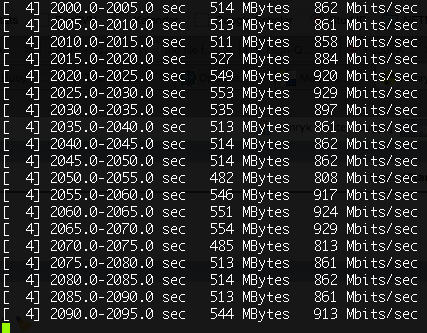
Running iperf between the two hosts (1 rusty PowerMac G5, 1 Intel cheese grater Mac Pro) over the management VLAN (without the ping-pong chain) gave about 940 MBit/s. With the ping-pong traffic amplifier, we got 800-930 MBit/s TCP throughput. Considering that the ping-pong traffic includes both the sent TCP data packets and the respective acknowledgements, the experiments could be concluded successful. A UDP test with iperf gave exactly the same numbers around 930 MBit/s between the two hosts, with and without the 10GE ping-pong. A quick test with a faster laptop instead of the old PowerMac on the left end gave 960 MBit/s UDP via iperf.
We tracked the average throughput on the switch ports via Nagios over the last week (see screenshots). Apart from an apparent timing calculation issue for the 10GE link (I need to re-visit my cisco traffic script), the measured throughput stayed steadily around the expected peak.


Which such a setup is quite useless for practical applications, the recently repaired C3750s kept effortlessly routing 20 GBit/s total traffic through their 10 used Gigabit ports. This also means that the (in terms of marketing and enabled features) modestly positioned 2960-Xs held their ground pushing around a total of 38 GBit/s without breaking a sweat (18 GBit/s full-duplex through the 10GE port, 20 GBit/s through the 11 used 1GE ports).
So apart from toying around, this experiment could be seen as an example how to push devices in a burn-in test before their actual deployment.